Contact UsQuick Quote
Tri-Rotor Pump Instruction Manuals
The instruction manual for each Tri-Rotor pump series is a valuable resource for information about your Tri-Rotor pump. These instruction manuals (with pictorialized parts list) are provided with every pump manufactured by Tri-Rotor. This includes any pump refurbished or repaired at the Tri-Rotor facility.
Each manual is organized in similar fashion. The manuals for each Tri-Rotor pump series include:
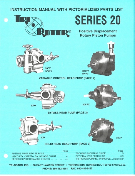
Series 20 and Series 20CP Instruction Manual
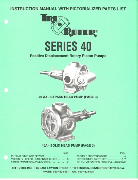
Series 40 Instruction Manual
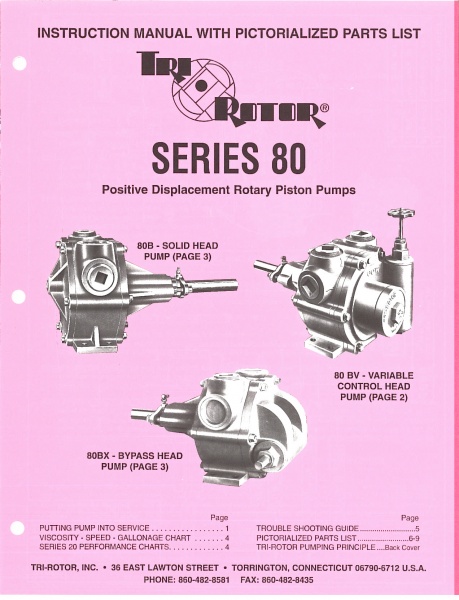
Series 80 Instruction Manual
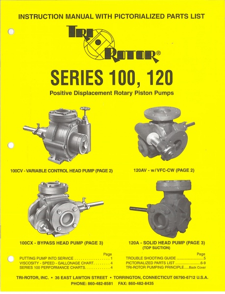
Series 100 and Series 120 Instruction Manual
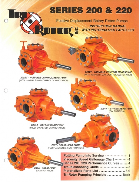
Series 200 and Series 220 Instruction Manual
If you have any questions about our pumps or information in our instruction manuals, please contact us.
Each manual is organized in similar fashion. The manuals for each Tri-Rotor pump series include:
- A dimensional drawing of each model the pump (bare pump only – no motor)
- Instructions on putting the pump into service including mounting and alignment recommendations. This includes instructions for the Variable Volume Control Head pump models, the Bypass Head pump models, and the Solid Head pump models.
- Instructions on adjustments to make in the field. These instructions include adjusting the control spring tension on the Manual Flow Control and the Vernier Flow Control as well as adjusting the relief pressure on the Bypass Head models.
- Notes on how to reverse the direction of rotation of the pump after it has been put into service
- Performance flow curves and maximum recommended pump speeds for various viscosities
- A Troubleshooting Guide
- An Exploded View
- Parts list (with pictures) for each pump model and option
- A full description of the Tri-Rotor pumping principle
Series 20 and Series 20CP Instruction Manual
Series 40 Instruction Manual
Series 80 Instruction Manual
Series 100 and Series 120 Instruction Manual
Series 200 and Series 220 Instruction Manual
If you have any questions about our pumps or information in our instruction manuals, please contact us.